The safety of elevator brakes is closely related to the safety of elevator systems, and the safety of brakes has gradually attracted the attention of the whole society. Elevator brakes are commonly used for maintaining and emergency braking of elevators, including braking during normal operation, emergency braking in case of abnormal situations, as well as braking devices for overspeed and unexpected movement. They play multiple roles in one brake and have a significant impact.
Among the numerous accident factors of brakes, the disappearance of remaining travel and the failure of brake holding caused by the top of the armature have gradually become a common phenomenon. Therefore, in the design and manufacturing process, reserving and ensuring the remaining travel, detecting the remaining travel allowance during elevator maintenance and repair is a key factor affecting the safety of brake holding.
1. Definition of remaining itinerary
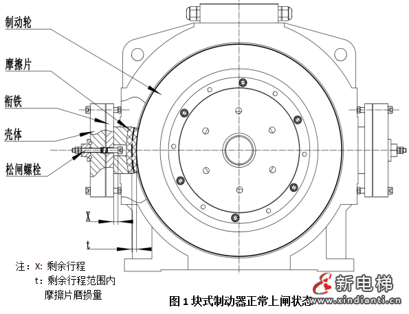
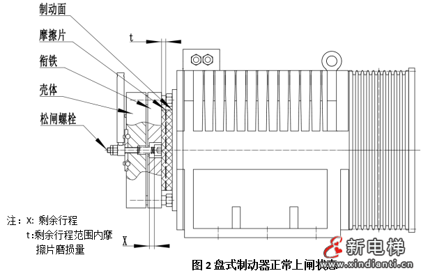
1.1 The remaining stroke of disc and block brakes refers to the range within which the brake release handle can still rotate after the brake is applied (with the brake pad tightly attached to the brake wheel), that is, the remaining clearance between the armature and the handle. As shown in Figure 1 and Figure 2, X represents the remaining stroke.
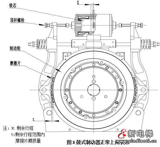
1.2 The remaining stroke of drum brakes refers to the distance that the armature (moving core) can still move after the brake is applied (the brake pad is tightly attached to the brake wheel). As shown in Figure 3, X represents the remaining travel.
2. Hazards of remaining itinerary disappearance
Zero speed "braking is the theoretical working state of elevator brakes. Theoretically, the brake friction plates should not wear out. However, in elevator testing, annual inspection, braking force testing, and other tests, as the elevator completes multiple brake applications, the friction plates may wear out to varying degrees, increasing the working stroke of the brake armature. After research, it has been found that in many operating conditions, especially for brake friction plates that have been used for more than 5 years, the actual wear is more severe.
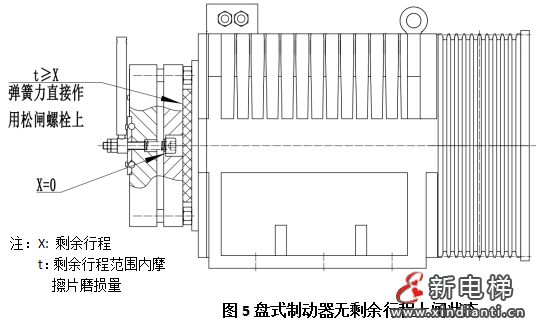
In addition, during the later use of the elevator, when the wear of the friction plate exceeds the allowable remaining stroke, the armature gradually approaches the brake wheel and experiences a dead end phenomenon. Although the electromagnetic force of the brake and the spring force of the brake spring remain in good condition, the spring force is completely applied to the brake release mechanism (as shown in Figure 4, Figure 5, Figure 6) and cannot be applied to the brake wheel, resulting in the disappearance of the braking torque.
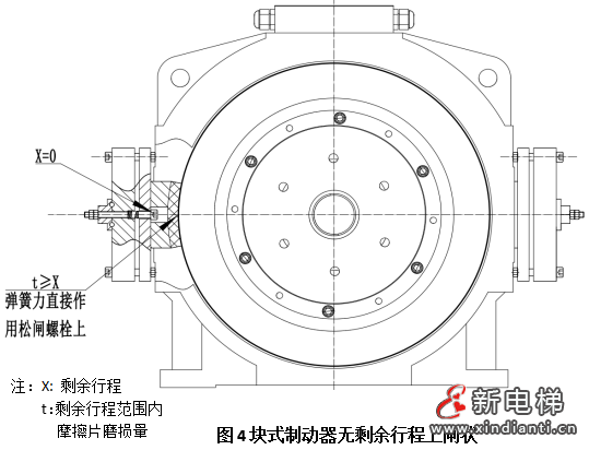
In the context of the rapid development of the elevator industry, the capabilities of design and manufacturing units and maintenance units vary greatly. Some non-standard manufacturers blindly imitate market products, have a poor understanding of the remaining travel, and do not reserve enough remaining travel in the design process, resulting in the disappearance of remaining travel and the occurrence of brake jamming when the friction plate wears out slightly; During the maintenance process, the focus of maintenance personnel is often mainly on the flexibility of the brake release action, often neglecting the inspection of the remaining travel. Therefore, it is necessary to reserve the remaining itinerary. If there is no remaining travel, the wear of the brake friction plate to a certain extent will easily cause the brake armature to jam (i.e. X=0, as shown in Figure 4, Figure 5, Figure 6), leading to the failure of the brake. So the remaining journey should also be a mandatory inspection item during each elevator maintenance.

However, regardless of the form of the brake, the remaining travel allowance reserved in the design will gradually disappear sooner or later as the wear of the friction plate increases. Therefore, compared to the design phase, it is more important to effectively check the remaining travel during maintenance to avoid potential safety risks.
3. Remaining itinerary detection
3.1 For disc and block brakes, after power off and braking (with the brake pad tightly attached to the brake wheel), use the matching brake release handle. The angle at which the brake release handle can still rotate is generally designed to be around 5 °, which is difficult to detect and mostly relies on sensory inspection on site.
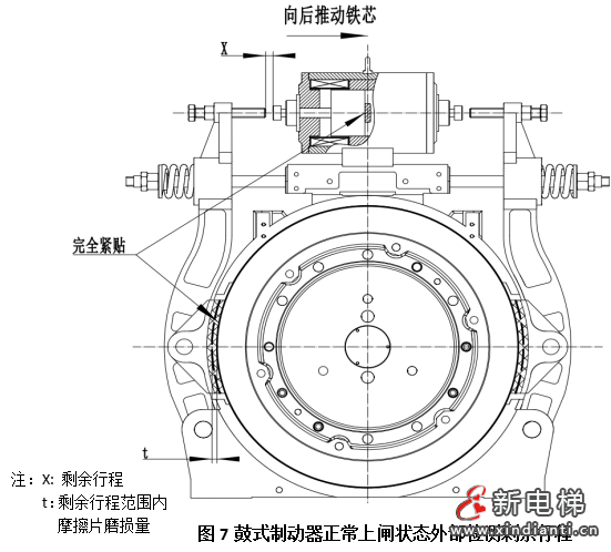
3.2 For drum brakes, after turning off the power and applying the brake (with the brake pad tightly attached to the brake wheel), push the armature inward to the limit, and use a feeler gauge to check the gap X between the brake armature (moving core) and the brake bolt. X is the remaining travel (Figure 7). This remaining travel design has a large margin and is easy to detect, and can be directly checked with a feeler gauge on site.
4. Remaining itinerary adjustment
4.1 For disc and block brakes, the designed residual stroke is small, and the impact of emergency braking on the reduction of residual stroke is significant. The usage frequency is small, and it cannot be adjusted on the whole machine. Either replace or remove the brake, and the adjustment frequency is frequent, resulting in high costs.
4.2 For drum brakes, the designed residual stroke is relatively large, and the impact of friction plate wear on the residual stroke is relatively small. The residual stroke can be adjusted before it disappears, and it is easy to adjust with low cost. Example of adjustment method, including step 1: In the power-off state, manually push the iron core to the innermost side, adjust the brake bolt so that the gap between the bolt end face and the moving iron core end face is about 2.5mm (adjusted during initial brake installation). Step 2: Power on the brake, open the brake, and use a feeler gauge to check the gap between 0.10-0.15mm. Use 0.1mm and 0.15mm feeler gauges to insert the gap between the brake wheel and the friction plate from top to bottom. The 0.10mm feeler gauge can pass through, but the 0.15mm feeler gauge cannot; a) When the gap is less than 0.10mm, rotate the adjusting bolt clockwise to adjust the required gap between 0.10-0.15mm, and then tighten the nut; b) When the gap is greater than 0.15mm, rotate the adjustment bolt counterclockwise to adjust the required gap to between 0.10-0.15mm, and then tighten the nut.
Note: The above dimensions are subject to the manufacturer's factory settings.
5. Summary
From the above, it can be seen that whether it is the drum brakes used in large quantities in the early days, or the disc brakes and block brakes widely promoted in the current and future markets, all legitimate manufacturers in the market have reserved necessary remaining stroke in their designs. The remaining stroke design of disc brakes and block brakes is relatively small, generally within 0.5mm, and the remaining stroke x decreases equally with the wear of the friction plate t; The remaining stroke of drum brakes is designed to be relatively large, usually around 3mm. In addition, the brake arm lever coefficient a exists (a takes the value of (0-1)), and the remaining stroke X is less affected by the wear of the friction plate t; The same amount of friction plate wear t, the remaining stroke X1=t of the disc brake, and the remaining stroke X2<t of the drum brake, theoretically, the structure and remaining stroke reserve of the drum brake can better ensure the service life and safety.
As the wear of friction plates increases, the remaining travel will gradually disappear sooner or later. Therefore, compared to the design phase, it is more important to effectively check the remaining travel during maintenance to avoid potential safety risks. We also call on the industry to pay attention to this.


